






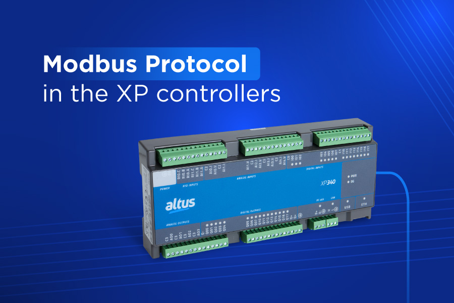
In the daily routine of the shop floor, the Modbus protocol remains the most widely used standard for interconnecting PLCs, HMIs, variable frequency drives (VFDs), and field instrumentation. Even so, small errors in addressing, response times, and data formatting frequently raise common questions.
Understanding how the Modbus protocol operates, along with the diagnostic tools built into Mastertool, is the fastest path to reducing the risk of unplanned downtime and ensuring the reliability of your control network.
That is why this article was created: to clarify some of the top questions received by our technical support team, helping those who already operate our Nexto XP controllers in their everyday routines. Read on through the following paragraphs.
What are the correct steps and the most common errors when configuring the Modbus driver in Mastertool?
Structuring the Modbus driver in Mastertool requires the correct association between the physical interface and the desired protocol instance. In the project’s device tree, right-click on communication channel COM 1 for RS-485 serial networks or NET 1 for Ethernet networks and add the appropriate Modbus device, such as Modbus RTU Master/Slave or Modbus Ethernet Client/Server. Next, symbolic mapping relationships are created, connecting the application variables to the network registers, and cycle times (polling) are configured for each request.
The most common error during the engineering stage is the overlap of register ranges in the protocol mapping table. When two requests attempt to access the same memory range, or when a DWORD variable occupies two 16-bit registers without reserving the subsequent address, the result is data corruption and random communication failures.
Another recurring mistake in the development environment is leaving unassigned allocations, indicated by question marks (?) in blocks and tables, which prevents code compilation.
Using Modbus Symbol is the most recommended alternative to avoid conflicts and memory address overlap. By choosing Modbus Symbol drivers (such as Modbus Symbol RTU Slave or Modbus Symbol Server), Mastertool automatically manages the symbolic mapping of application variables, eliminating the need for manual allocation to direct physical input (%I) and output (%Q) addresses.
As a result, it is possible to eliminate the risk of accidental data overlap when using variables with different memory sizes (such as WORD and DWORD), making application maintenance and expansion simpler.
Why do Modbus values read on Nexto XP differ from the scaling of third-party devices?
The discrepancy between the values read in the PLC and the scale displayed on field instruments depends on analog conversion and data formatting. Nexto XP controllers use a scale of 0 to 30,000 counts to represent standard 0 to 10 V or 4 to 20 mA analog signals, whereas transmitters and indicators from other manufacturers often operate with internal ranges of 0 to 10,000, 0 to 4,095, or scaled integer values.
A temperature sensor, for example, might transmit a value of 250 to represent 25 °C. In this case, the programmer must apply a scaling block or a division by ten within the PLC logic to normalize the reading before using it in the process.
Another recurring cause of inconsistent shop-floor readings is byte order inversion in 32-bit variables. The 32-bit ARM processor in the Nexto XP series uses little-endian memory organization, where the least significant byte is stored at the lowest memory address. When the controller reads a 32-bit register, such as a REAL floating-point number or a DWORD integer, from a slave device that transmits in big-endian format, the bytes arrive swapped, resulting in incorrect values on the programming software screen.
The solution to this issue is simple: just apply a byte-swap conversion function in Mastertool before utilizing the variable in the control logic.
How to resolve Modbus addressing issues in Nexto XP when communicating with an HMI
Addressing conflicts between a Nexto XP and HMIs generally stem from the difference between zero-based and one-based indexing.
In the Modbus protocol specification, the Holding Registers table starts at offset 0. Most HMI software (such as our P2, X2, and Axon series), however, adopts 4x or 400001 notation, where the number 1 points to the first physical register. If the systems integrator configures the HMI to read variable 400001 and, in MasterTool, the slave mapping is set to address 1, a one-position offset occurs, causing the HMI to display data from the adjacent register.
Using the Absolute Start Address column in MasterTool is the key to configuring exact register matching. The software automatically calculates the equivalent absolute address for each mapping created (for example, a Holding Register mapped at address 1 generates absolute address 400001).
To ensure commands sent from the HMI are written correctly, you must also confirm that the PLC variables were not accidentally configured as read-only in the driver, and that the data type defined on the HMI screen (INT, WORD, or REAL) matches the exact memory size declared in the Nexto XP controller.
NOTE: It is also important to remember legacy equipment, where Modbus addresses use 5 digits, so you must refer to the equipment manual to make the appropriate correlation. For example:
For reading digital inputs, Input Status is typically used:
Input Status 1 = 10001 = 100001
For reading and writing digital data, Coil is used:
Coil 1 = 00001 = 000001
For reading analog data, Input Register is used:
Input Register 1 = 30001 = 300001
For reading and writing analog data, Holding Register is used:
Holding Register 1 = 40001 = 400001.
How to resolve Modbus TCP communication failures between the XP340 controller and a variable frequency drive
Modbus TCP communication failures between the XP340 controller and variable frequency drives (VFDs) are typically related to subnet parameters, service ports, and slave device requirements.
The first step in restoring the link is to verify that the XP340’s NET 1 Ethernet interface and the drive’s network card belong to the same IP range, and that TCP port 502 is not blocked by a firewall. Furthermore, even when operating over TCP/IP, most VFDs require the Slave Address (Unit ID) parameter to be set to the correct numerical value (usually 1), as the drive’s internal firmware drops Ethernet packets whose header contains a Unit ID that differs from the configured value.
The internal processing latency of variable speed drives requires adjusting timeout values and limiting simultaneous requests. Because drive microprocessors prioritize motor control loops, their response time to network requests is usually higher than that of a PLC. If the Communication Timeout parameter in the Modbus Client driver on the XP340 is set to short values (below 100 ms), the controller cancels the message before the drive responds, causing intermittent faults.
To resolve this issue, increase the timeout value in the MasterTool requests tab to between 500 ms and 1000 ms, and set the limit for simultaneous requests per device to 1.
How to adjust RS-485, RS-232, and TCP Port communication parameters on a Nexto XP controller
Parameter configuration for the RS-485 serial channel on the Nexto XP is performed directly in the properties of interface COM 1 within MasterTool. The systems integrator must select the desired baud rate (from 2400 to 115200 bps), parity (None, Odd, or Even), 8 data bits, and 1 or 2 stop bits.
If the Nexto XP controller is located at either physical end of the RS-485 bus, it is essential to check the option to enable internal termination in the software or install dedicated modules to prevent signal reflections.
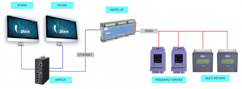
The NET 1 Ethernet interface comes factory-configured with default IP, subnet mask, and gateway values, which can be easily adapted to your plant network. The default IP address is 192.168.15.1, with a subnet mask of 255.255.255.0 and a gateway of 192.168.15.253. For the Modbus TCP protocol, the default listening port is 502, but users can assign alternative ports (between 2 and 65534) when creating additional server instances, avoiding the use of reserved system ports.
IP address and port changes can be saved by downloading the application via MasterTool, using the MAC Easy Connection scanning tool, or directly through the controller’s embedded System Web Page.
How to handle timeout, intermittent, or communication loss errors in Modbus on the Nexto XP
Agile troubleshooting of Modbus protocol interruptions relies on monitoring the global data structures provided by MasterTool. In the GVL System_Diagnostics and GVL ReqDiagnostics lists, operators can track the communication counter (wCommCounter), the error counter (wCommErrorCounter), and the eLastErrorCode variable in real time.
The appearance of error ERR_CONNECTION_TIMEOUT (code 40) or ERR_RECEIVE_TIMEOUT (code 42) indicates that the remote device failed to send a response within the defined time limit. On the other hand, the presence of the ERR_CRC error (code 2) signals electrical noise, attenuation, or a parity/baud rate mismatch on the RS-485 network cabling.
Visual inspection of the status LEDs on the Nexto XP panel also provides immediate alerts regarding equipment conditions: the DG (Diagnostics) LED double-flashes to indicate active faults, and the RS485 port LED indicates communication activity.
In Ethernet networks, for intermittent failures that are difficult to isolate, the Nexto XP System Web Page provides an embedded Network Sniffer tool. It captures physical interface traffic and generates a .pcap file, allowing you to analyze packets directly in Wireshark to confirm whether the PLC is sending requests and if the slave is responding within the expected window.
Where to find technical support and additional documentation
To further refine your project settings or clarify specific application queries, Altus provides all required technical documentation and qualified support.
The full manuals for the Nexto XP series and MasterTool IEC XE can be downloaded for free from our download center or via the buttons below.
Finally, an extensive collection of tutorials is available in our knowledge base, simply click here.
Our YouTube channel features over 90 videos dedicated exclusively to Nexto XP controllers.